In these new series of articles, I want to share my experimentation with remote sensors and mobile access; nowadays there is a lot revolving around mobile and mobility, in addition to the “Internet of Things” widely announced – I don’t know if the Internet of Things will ultimately happen in the way predicted, but I wanted to have my go at it.
This exercise aims to a very simple goal: enable mobile access to a remote sensor reading.
In the followings, I will introduce the experiment I crafted for this exercise and document each module.
Introduction
From the goal/delivery which I explained above, “enable mobile access to a remote sensor reading“, the first thing, is that I drafted a schema:

In this schema I already marked down some constrains for implementation, that is the use of the XBee modules: normally I try not to bind myself to implementation constrains while drafting the architecture; this is more dictated by the fact that I had these modules sitting in a box from past projects, so I wanted to put them to new use. The same applies for having a sensor to actually measure some sort of distance.
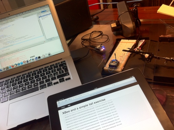
Here is a picture of all the modules and components working nicely all together:

In the picture above:
- background, upper-right: the distance sensor connected to the XBee router module mounted on a prototyping breadboard
- background, upper-left: the XBee coordinator module which receives the reading, connected to the MacBook which acts as the server implementation to access the reading’s data from the Intranet
- foreground: an iPad accessing the web application hosted on the server which provides the reading’s data live, similarly to the Linux tail command
Remote sensor reading
In this section I will detail the lower part of the architectural schema and how the XBee modules enable for the remote sensor reading.

In the picture above, from right to left:
- The distance sensor, mounted on the fixed-mounting brackets
- The XBee router module, mounted on the prototyping breadboard: this is connected to the distance sensor
- The XBee coordinator module, this is connected to the server
The distance sensor is in fact a transducer which provides an analog signal related to the distance seen, in this case, up to the Post-it note block also mounted on the fixed-mounting brackets. The XBee router -the one mounted on the prototyping breadboard- performs the Analog-to-Digital (ADC) conversion of this analog signal into a reading transmitted via the ZigBee protocol, to the XBee coordinator module.
One interesting part in this section is actually the electrical schema on the distance sensor side:

The schema is quite simple but in the details:
- The distance sensor is a Sharp 2D120
- The Sharp 2D120 requires power supply and complementary electrical circuit as documented in its own datasheet, in this case I bought it from Phidgets as P/N 1101 because I found a nice boundle with the Sharp 2D120 which is Phidgets P/N 3520.
- The AIN signal out of the Phidgets 1101 will vary 0-5V, while the ADC on the XBee is expecting a 0-3V: in this case I brutally cut the AIN signal in half with R1 and R2 which are 220ohm. This brutality is justified by my priority in having some contingency out of the Phidgets 1101.
- The block marked IC1 in the schema is actually a “break-out” module called XBee Adapter board from Parallax P/N 32403 which is used to conveniently mount the XBee on the standard hole sizes of the prototyping breadboard.
- schema IC1-pin 12 corresponds to Parallax 32403 pin VSS which is ground, which in turn corresponds to XBee Pin 10 GND for ground as well
- schema IC1-pin 13 corresponds to Parallax 32403 pin VDD which is +5V, which in turn will provide +3V to the Xbee module
- schema IC1-pin 23 corresponds to Parallax 32403 pin IO1, which in turn corresponds to Xbee Pin 19 D1, which is Analog input 1 or Digitial input 1 – in this case it’s setup as Analog input 1
Next is to setup the XBee by configuring and flashing the correct firmware on them.
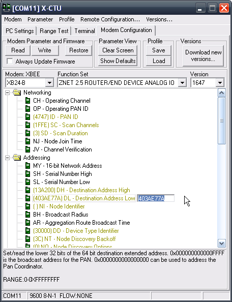
Starting from the XBee router module, the one in charge to perform the ADC of the distance analog signal and transmit it.

The XBee router must be setup in such way to connect to its coordinator, so you will notice the Destination address has been set to the address of the coordinator, ending with 403AE77A. I also setup in this case the Personal Area Network as 4747, from the X-CTU software appears not a valid address but accordingly to other reference is perfectly allowed.

Next is to setup pin D1 of this XBee router module as ADC. Once also this settings has been saved, time to flash the firmware and configuration on it with the appropriate function in the X-CTU software.
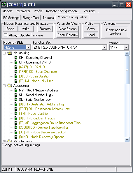
Then it’s turn for the XBee coordinator module; in this case it’s very simple, as it’s just to setup it as a coordinator:

Then also time to save and flash this firmware as well.
The XBee coordinator is mounted on the XBee USB Adapter board from Parallax P/N 32400, which is very helpful to connect it via USB as a Virtual Com Port (VCP) thanks to the mounted FTDI chipset. This will auto-magically wire it a serial port /dev/tty.usbserial-xxxx on the Mac, although accessing it from Java – which is my preferred programming language of choice – is not the easiest thing.
This overall setup of the two XBee modules can be proved quickly by using a Processing sketch – as I was saying in an earlier post, it’s a very handy prototyping environment – as documented on the xbee-api Google code site, just to be sure it’s working already.
To be continued
This is the conclusion for the remote sensor access part, in follow-up post(s) I will explain the implementation details applied on the server, specifically the Java web application, xbee-api and Spring used, HTML5 and jQuery to access these readings and data via mobile access.